Read time: 10 minutes
Overview
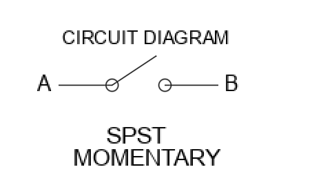
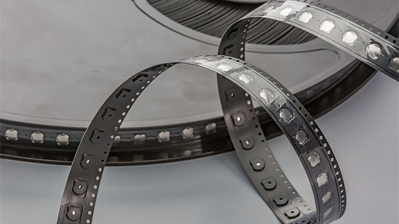
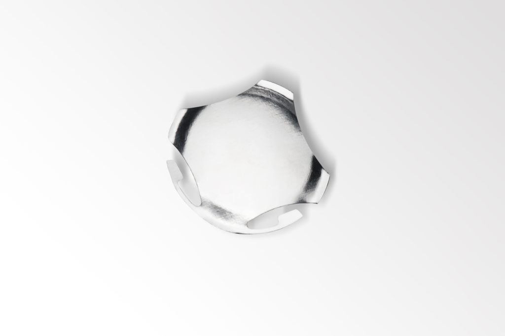
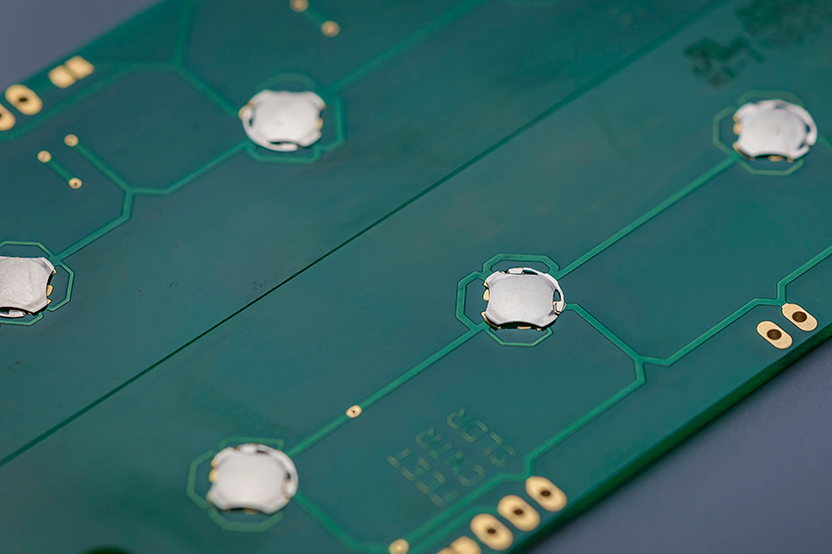
Snaptron’s S-Series domes, SMD switches, are standard four-leg metal dome switches with two solderable tabs. The tabs allow the dome to be soldered directly to a printed circuit board or flex circuit with a surface-mount technology (SMT) machine. Like standard tactile domes, the solder dome is a normally open momentary contact (SPST) that provides a crisp tactile feel, letting you know that a button was pressed.
BENEFITS
- Easily integrate the solder dome into your existing SMT automation process
- Reduce overall build time and eliminate steps to final product assembly
- Improve placement accuracy due to the elimination of manual placement
- Eliminate the use of adhesive or tape to simplify assembly
- Lower the cost of labor for dome placement
DOME APPLICATION AND ASSEMBLY
Placement and Adhering Domes with Soldering
Traditional methods of adhering metal domes to the circuit board require adhesive tape or placement into spacer pockets. This process is typically done semi-automatically or manually and requires an assembler. A major benefit of a solder dome is the ease of assembly and the ability to use automated equipment to place these domes. This takes the time and cost of manual labor out of the equation and eliminates the mandatory use of cover tape on loose domes during the assembly process.
The dome’s design has tabs that get soldered to the substrate in two locations without impacting the switch’s performance. You can either manually or automatically solder the dome in place using SMT assembly systems.
Seven Steps to SMT Assembly
Snaptron recommends you follow the below steps to solder the dome to the substrate:
- Solder paste and flux are applied to the PCB on the pre-determined solder pads either with a stencil or a printing machine.
- An SMT machine automatically places components, including the dome, on a PCB’s appropriate locations.
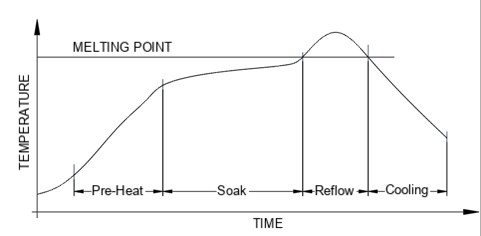
- The PCB, either fully or partially populated with components, is then passed through a reflow soldering oven with different heat zones. Many solder pastes require at least three heat zones. The first zone gradually increases the temperature of the board, components, and solder paste. The second zone brings the solder paste to its melting point to create the solder joint with the component. The last zone reduces the components’ temperature and allows the solder paste time to solidify, thus creating the solder joint.
- If additional components need to be added, repeat this process. Snaptron recommends applying the domes in the last reflow process if there is more than one.
- Before final assembly, the PCB is sent for quality inspection to ensure all components have adhered correctly or need to be reworked manually.
- At this point, and only if needed, a layer of cover tape can be added to seal the dome switches to keep out contaminants.
- Finally, the PCB will go through final product assembly and testing.
Snaptron’s domes are very reliable. More importantly, their pre and post-sales service are very good and dependable–this is a key factor to the success of our supply chain and business.
-Steven Wee, Production Manager
Process Considerations for Solder Domes
The S-Series domes have special considerations for the assembly process. Please consider the following:
- Mechanical placement will involve a pressing force onto the dome. Please ensure the placement force is less than the rated actuation force of the dome.
- Snaptron recommends using a ‘No-Clean’ Flux for dome soldering. Domes can have water spots. Spot deposits could affect dome performance.
- If desired, a cover tape layer can be added to seal the switches from components or handling damages after solder reflow.
- If the dome is covered with tape, its tactile feedback is minimally affected. While the tape may slightly dampen the effect, this can be minimized by ensuring proper ventilation. The dome should still provide a consistent and reliable tactile response.
- It is not recommended to use glue or other bonding methods to adhere to the domes before soldering.
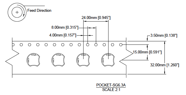
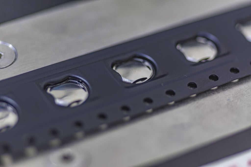
- Ensure the dome’s feed direction aligns with the machine’s requirements. Misalignment may lead to improper placement or damage. The feed direction is outlined on the drawing.
SMT Machine Considerations
The first thing to consider when soldering a dome is understanding the type of SMT machine used in your production process. Some SMT machines support small volumes, such as prototyping, for example. While some machines support large volumes and high-speed production lines. Specific machines are best suited for single-sided components, pass-through components, surface mount, or double-sided soldering. SMT technology also varies by fully automated, manual, multi-head, or a combination of these options. Always be sure to understand the inner workings of your machine before prototyping or production of your final product.
Soldering Process and Considerations
Solder Types and Thermal Profiles
Solder pastes contain an alloy of metals that, when heated and cooled, create a solder joint between two substrates, in this case, a PCB and metal dome switch. Depending on the type of solder paste, they also require different thermal profiles.
Traditional reflow soldering is performed with either a leaded solder, lead-free solder, low-temperature solder, or other, depending on the components being placed and product requirements. In addition, solder pastes vary in particle size. Therefore, it is important to select a solder that adequately adheres to a component while not requiring a temperature that may damage the component, another component, or the PCB.
Leaded solder (SnPb) is a blend of lead and tin that provides a tough solder joint and is often used when the end product is utilized in rugged environments or exposed to harsh environmental conditions. In some cases, leaded solder is easier to work with and more affordable due to its high lead concentration. Leaded solder requires lower heat than many other solder types and typically needs to run through a thermal profile with temperature stages at 120°C/150°C/225°C for a specified time. Although a very reliable option, one key consideration is where your product will be sold. Now, many regions of the world require that all lead components, including leaded solder, are free from commercially available products due to their negative environmental impact and concerns regarding human health.
SMD Parameters
| Average ramp up rate | 4°C/s max |
| Preheat time | 120s max |
| Soak temperature | 155-175°C |
| Soak time | 60-100s max |
| Peak temperature | 265°C (509°F) max |
| Duration above 217° | 60s max |
| Ramp-down rate | 6°C/s max |
| Moisture Sensitivity Level (MSL) | 1 |
| Reflow Cycles | 1 |
Lead-free solder (SnCuAg) is a viable alternative to leaded solder that significantly reduces health concerns and environmental impact. Lead-free solder typically has a high tin concentration, making this the most expensive option. In addition, tin has a higher melting point with a thermal profile of 150°C /190°C /250°C. Lead-free solder works well if the design and components withstand higher heat exposure.
If you require a lead-free option but the design includes components sensitive to heat, there are low-temperature solder pastes. These pastes are typically a mixture of Tin and Bismuth (SnBi), although many other alloy options are available. SnBi has a much lower melting point and works well with components that are sensitive to heat exposure. The three-zone thermal profile for SnBi typically falls around 100°C /130°C /180°C. However, due to the chemical makeup of the solder pastes, the solder joint may be weak or insufficient to create a long-term bond. Therefore, it is always important to review the design, components, and solder type options early in development to determine the best solder paste for the product.
Determining Solder Paste Amount
You must understand the space constraints, the distance between components, and the footprint of the metal dome to determine an appropriate amount of solder paste. In general, the recommended amount of paste for soldering a dome should be approximately 40% – 50% of the area of the solder pad. If too much solder paste is added, the solder may move into the solder keep-out area and either cause the dome to fail or prevent the dome from making electrical contact. On the other hand, if too little solder paste is added, the solder joint may not be strong enough to withstand the full range of presses and can cause an early switch failure.
Solder Wicking or Solder Drainage
Solder wicking or solder drainage can greatly impact the dome’s performance or provide an inadequate solder joint. It is important to inspect the solder movement and solder joints to ensure a long-term bond and long-lasting performance of your SMD dome.
To prevent the over-application of solder paste resulting in an increased risk of solder wicking along the dome’s solderable tabs, Snaptron recommends using a 5mil (0.13mm) thickness solder stencil with fresh solder paste on every paste application.
We also recommend considering best flux outgassing practices to ensure contaminated flux deposits are removed during reflow. Please follow recommended procedures from the solder paste or flux manufacturer. Snaptron also recommends allowing at least 50mil separation between the dome and other SMT parts near the dome’s solder tabs.
Double-sided Soldering
In many cases, components are placed on both sides of a PCB. This is performed by soldering one side and then the other in a two-step process. If placing the domes during the first soldering step, adhesive material like Kapton (polyimide) may be added after soldering to hold the domes in place during the reflow of the other side. This material may fully cover the domes, but this is not required.
Sealing Components Post-soldering
For cases where you anticipate an abundance of contamination due to environmental exposure or board wear, it is important to know that the solder dome is not fully sealed. PET or polyimide can be added to create a fully sealed surface over the dome to keep out contaminants. However, there is no need for this adhesive material to be accurately positioned, as would be the case when the domes are placed with the adhesive.
Solder Dome Performance Before and After Soldering
In general, you can expect minimal changes in the performance of your solder dome before and after soldering. You may see a slight rise in trip force and a change in tactile ratio. When selecting an SMD dome, we recommended that you validate the dome’s performance and fine-tune the amount of solder paste and thermal profile in your SMT process before final assembly.
While Snaptron recommends using a no-clean flux, any process involving a wash cycle should consider the following. It is important to inspect the solder joints after washing to ensure that the solder tabs are adequately adhered to and were not damaged during the high-pressure wash cycle. A good way to test this is to measure the resistivity of the dome after soldering and washing to ensure the dome is performing as expected. On occasion, water or solvent may build up under the dome. This needs to be removed before the final assembly.
Note: Excessive water or air pressure may damage the dome and solder tab or break the solder joint.